
zForce AIR™ can be used for different purposes such as touch and gestures. Depending on what purpose the module should fulfill the assembly requirements will differ. Also different industries have different standards and demands to follow by. In general, mid-air detection applications will require lower mounting tolerance.
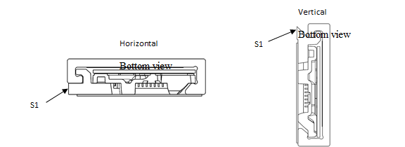
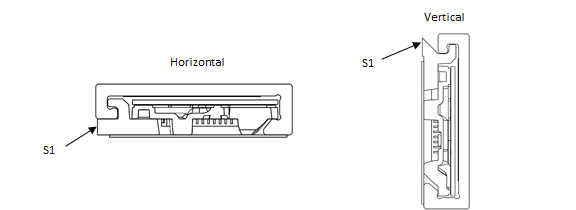
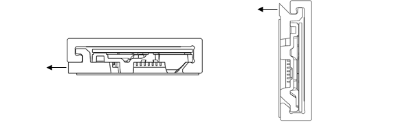
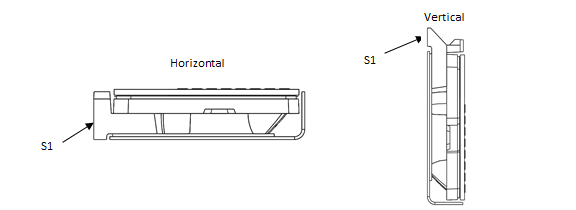
Vertical or Horizontal IntegrationzForce AIR™ comes in two types; one is designed to be integrated horizontally and the other vertically. This is to allow different types of assembly possibilities and better fit the available space in the host system. The two designs are built on the same concept, but by using two different front light pipes the light path is either unaffected or bent 90°.
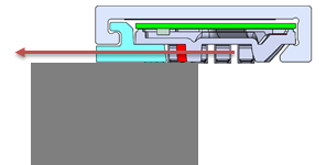
HorizontalLight is sent straight out and enables an active area in front of the module (in the same plane).
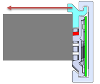
 Vertical
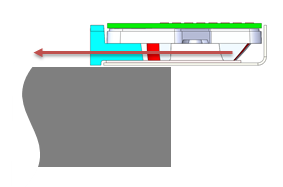
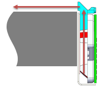
Light is bent 90 degrees within the module. This allows the module to be assembled vertically but still enables an active area in the horizontal plane.

-
- Double adhesive tape – for smaller sizes this can be used alone to hold the zForce AIR™. The Host System geometry needs to provide a flat supporting surface.
- Snaps – Customer geometry provides some sort of snap features holding the Module in place. These must be developed for each case to fit the Host System cover and the surrounding.
- Sandwiched – the zForce AIR™ is mounted by pressing the zForce AIR™ between Host System exterior cover and display. A structure (ribs, foam gasket or adhesive) is needed to make sure zForce AIR™ cannot move.
Important for all assembly solution is to make sure the supporting surface for zForce AIR™ is flat. A non-flat surface will result in floating issues; these issues grow with the size of the touch Active Area.
Important factors to consider for integration- Light path must be kept free.
- If an external window is used in front of the zForce AIR™ it must fulfill the optical requirements listed in Optical Requirements on External Optical Surface.
- Rotation of the zForce AIR™ must be avoided or minimized since it will affect floating. This becomes more sensitive with growing touch Active Area sizes. For mid-air detection application this is less sensitive.
- The assembly precision of zForce AIR™ in x- and y- direction determinate the precision of the touch Active Area position.
- The zForce AIR™ unite needs to be protected from outer pressure/forces that can redirect the direction of the light by bending the zForce AIR™. The most common cause of bending is when unit is mounted on a non-flat surface.
Recommendations for the distance between light plane and host surface.
Recommendations and TolerancesMechanical integration of zForce AIR™ and assembly tolerances has a direct impact on touch accuracy. For this reason relaxed assembly tolerances might in some applications impact on the perceived touch performance.
The best user experience is achieved when the projected touch Active Area from the zForce AIR™ perfectly overlaps the intended touch sensitive area on the host device, for example, the active area on a display. Relaxed tolerances can lead to missed touches and increased floating.
Translational Tolerances
Translational tolerances affects the overlap between the display AA and the touch AA – e.g. if the touch module is translated 0.5mm in x-direction there will be a systematic touch offset of 0.5 mm for the complete system in x-direction.
A positive translation in z-direction will not affect the touch accuracy in the system, but it can affect the perceived touch performance, since it can lead to increased floating. A negative translation in z-direction should be avoided since parts of the IR-light will be blocked which lead to reduced touch performance.
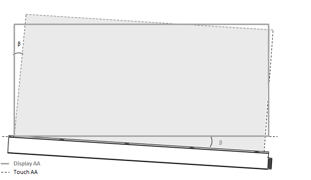
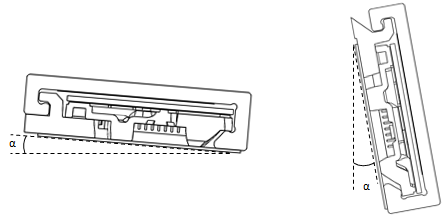
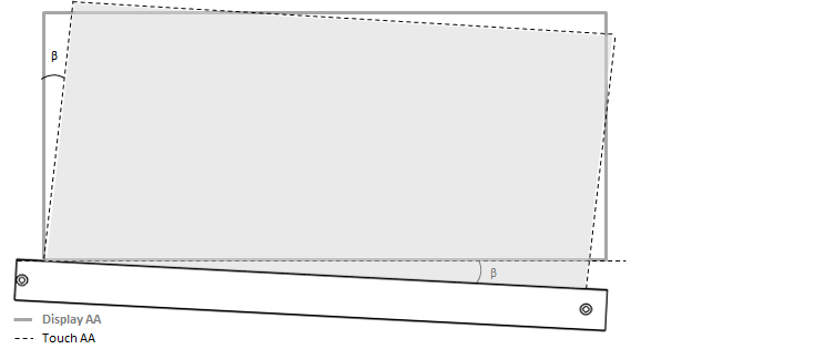
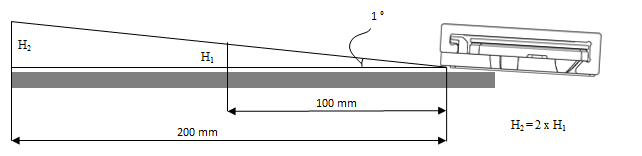
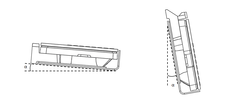
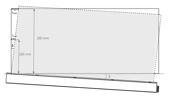
Rotation of ModuleThere are two types of rotations that can affect the performance; defined as the angles α and β. Angle α affects the floating and angle β affects the overlap between the display AA and the touch AA. Both these issues will grow with larger display sizes. The angles are exaggerated in the picture to better illustrate the problem.

How sensitive zForce AIR™ is for assembly rotations is direct linked to the size. For example, if angle α is one degree, the rotation will give twice the flouting at 200 mm compared to 100 mm.
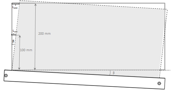
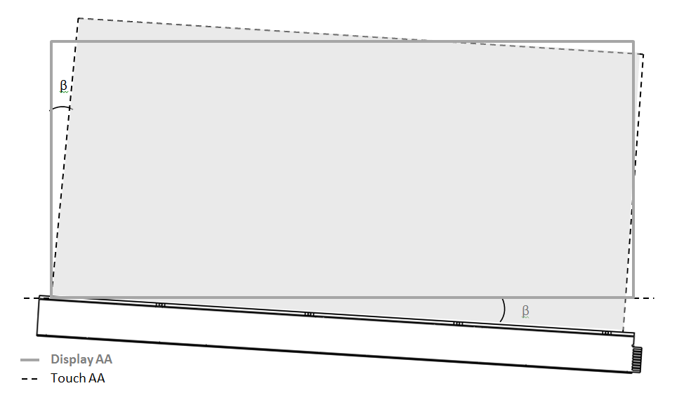
Rotational Tolerance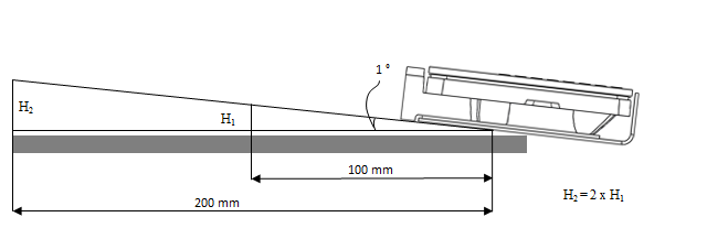
If angle β is one degree, the touch AA will be tilted twice as much at 200 mm compared to 100 mm.

Note: Angles and distances are exaggerated in the picture to better illustrate the problem.
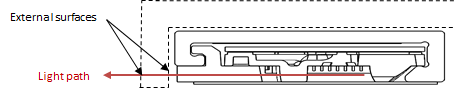
Optical surface S1Surface S1 is the only optical surface visible on the outside of the Module. This surface must be handled with extra caution. The light path must always be kept free, therefore no screw bosses etc. are allowed in front of it.

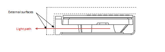
External Optical Surface
External optical surfaces are all surfaces placed between the sensor and the desired touch active area, usually in form of a plastic or glass “window”. It is of high importance for the function that these surfaces fulfil the optical demands stated in Optical Requirements on External Optical Surface. However, it is important to know is that each optical surface that the sensor light need to pass through will reduce the recorded signal levels, even though the requirements are fulfilled, which in some applications might reduce the detection range.
Document generated by Confluence on Sep 11, 2025 11:01