
The command looks a bit different depending on if the value is <= 127 or >= 128.
Red = Finger, and Blue = Idle.
In order to set the Idle and Finger frequency to a value <= 127 the following command can be used:
EE 0C 40 02 00 00 68 06 80 01 3F 82 01 3F
To set the Idle frequency <= 127 and Finger >= 128:
EE 0D 40 02 00 00 68 07 80 02 00 C8 82 01 3F
To set both Idle and Finger frequencies to >= 128:
EE 0E 40 02 00 00 68 08 80 02 00 C8 82 02 00 C8
The zForce AIR does not support Stylus mode, and setting the stylus frequency does not do anything.
This section will exclude the I2C protocol notations and only describe the ASN.1 payload.
A packet can contain one, two or three Touches, and optionally a timestamp. On packets where the timestamp is not included, the 58 02 TT TT bytes are missing from the end and the length bytes are adjusted accordingly, For One touch (below), F0 15 in the beginning will be F0 11 and A0 0F in the middle will be A0 0B. The same bytes are decreased by 4 for Two and Three touches.
One TouchA packet that contains one touch will look like:
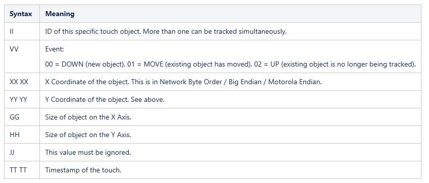
F0 15 40 02 02 00 A0 0F 42 09 II VV XX XX YY YY GG HH JJ 58 02 TT TT
where the data is defined as follows:
A packet that contains two Touches will look like:
F0 20 40 02 02 00 A0 1A 42 09 II VV XX XX YY YY GG HH JJ 42 09 II VV XX XX YY YY GG HH JJ 58 02 TT TT
where the first "II" and the following bytes up to and including "JJ" are from the first touch, and the second "II" and the following bytes up to and including "JJ" are from the second touch.
Three TouchesA packet that contains three Touches will look like:
F0 2B 40 02 02 00 A0 25 42 09 II VV XX XX YY YY GG HH JJ 42 09 II VV XX XX YY YY GG HH JJ 42 09 II VV XX XX YY YY GG HH JJ 58 02 TT TT
Setting the Touch Active Area should be done before enabling the device with the ENABLE request.
To invert the X axis, replace "84 01 00" with "84 01 FF" in the requests below (Near the end).
To invert the Y axis, replace "85 01 00" with "85 01 FF" in the requests below (Last bytes in sequence).
Inverting an axis does NOT rotate the coordinates, it simply inverts that axis.
The command to set the TAA is different depending on if a value is between 0-127 or if it is higher.
In the examples below a value between 0 and 127 will be represented by the value 0x3F (63) and a value from 128 and up is represented by the value 0x200 (512).
Red = Xmin. Blue = Ymin. Green = Xmax. Purple = Ymax. The Axis reversing bytes are not colored.
Xmin <= 127, Xmax >=128, Ymin <=127, Ymax >=128: Simply modify the correct byte(s) according to the desired limit.
EE 1C 40 02 02 00 73 16 82 14 80 01 3F 81 01 3F 82 02 02 00 83 02 02 00 84 01 00 85 01 00
Xmin >= 128, Xmax >=128, Ymin <=127, Ymax >=128: Simply modify the correct byte(s) according to the desired limit.
EE 1D 40 02 02 00 73 17 82 15 80 02 02 00 81 01 3F 82 02 02 00 83 02 02 00 84 01 00 85 01 00
Xmin <= 127, Xmax >=128, Ymin >=128, Ymax >=128: Simply modify the correct byte(s) according to the desired limit.
EE 1D 40 02 02 00 73 17 82 15 80 01 3F 81 02 02 00 82 02 02 00 83 02 02 00 84 01 00 85 01 00
Xmin >= 128, Xmax >=128, Ymin >=128, Ymax >=128: Simply modify the correct byte(s) according to the desired limit.
EE 1E 40 02 02 00 73 18 82 16 80 02 02 00 81 02 02 00 82 02 02 00 83 02 02 00 84 01 00 85 01 00
Document generated by Confluence on Sep 11, 2025 11:01