
Customer Documentation: Neonode® Touch Sensor Module User's Guide : .Sub Touch Active Area v2.2
Introduction
The Touch Sensor Module can be adjusted by changing the module's device configuration. By configuring these settings, the size or orientation of the Touch Active Area (TAA) can for instance be modified. Device Configuration is implemented according to the ASN.1 protocol, where most of the parameters can be configured in Workbench or zForce SDK. As for all changes to the device configuration, the new configuration will be stored in RAM. Meaning that the new configuration will have to be applied after each reboot. Please refer to section Device Configuration List to find all implemented parameters.
Index
Axis Orientation
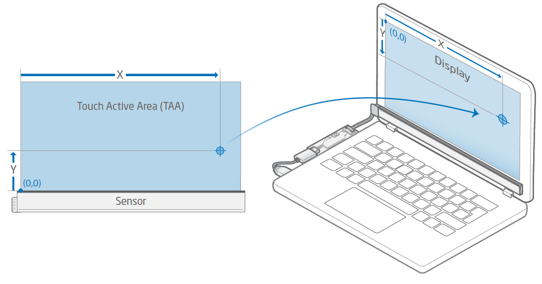
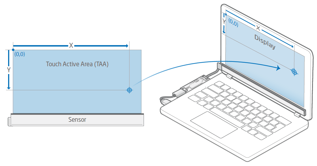
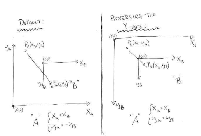
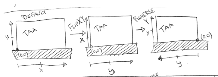
When mapping a reported touch from the Touch Active Area to a display, it is important that the orientation of the TAA, as well as the display are taken to account. When positioning a Touch Sensor Module over a display to achieve touch functionality, both systems needs to be co-aligned in order for a reported touch to be projected in the same corresponding position of the screen. If both systems are not oriented in the same way, the reported touches are going to be reversed depending of the setup. Luckily, the orientation of the reported touches can be configured to counter this by using ReverseX/ReverseY or FlipXY in Device Configuration. These settings rotates/flips the given coordinates of the reported touches, which allows a more setup variations.
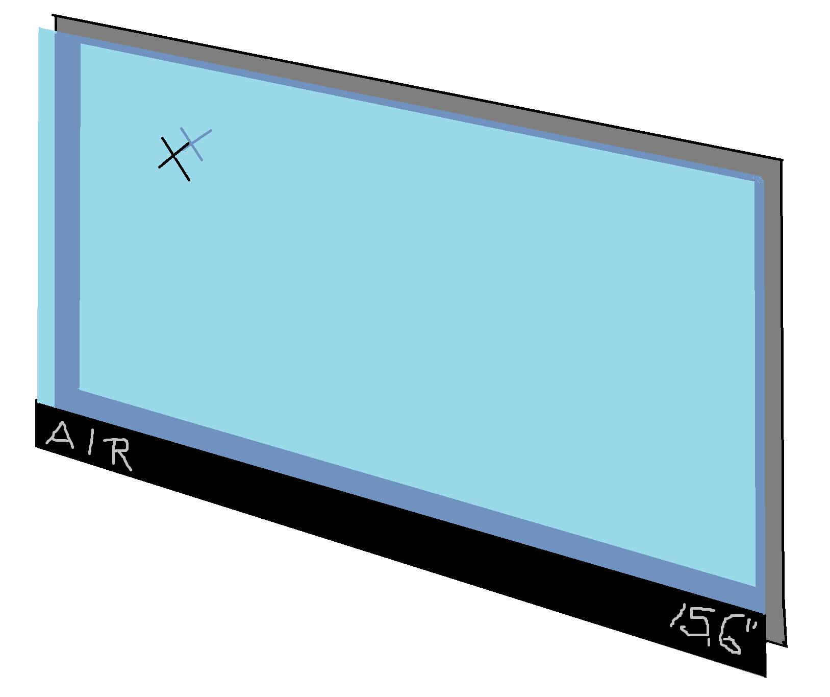
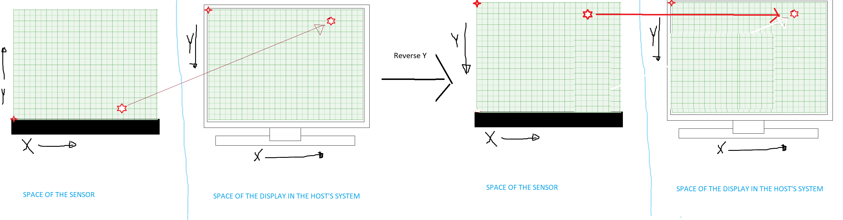
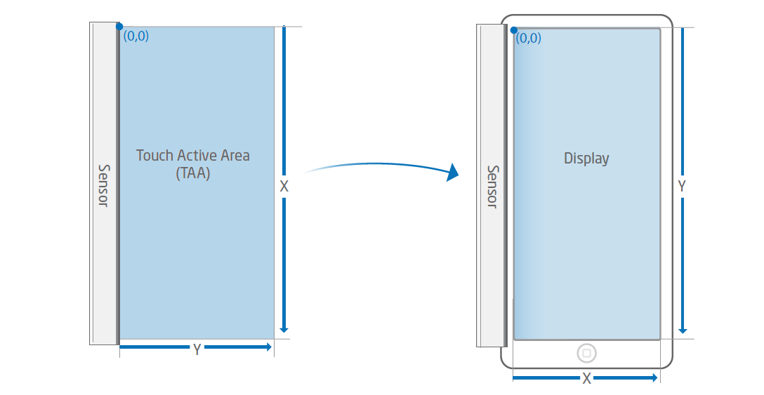
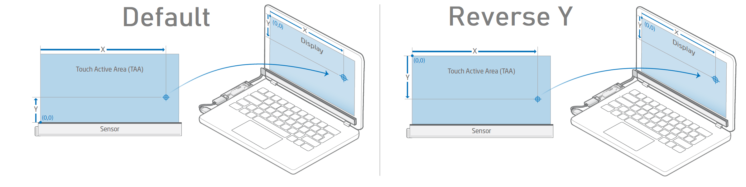
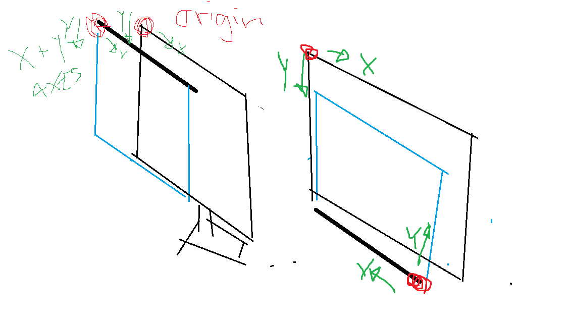
Almost all displays (OS) have their origin positioned at the upper left corner of the screen, where the x-axis points in the direction to the right, with the y-axis pointing downwards. The origin of the sensor module's Touch Active Area is positioned on the left hand side, when having the TAA facing downwards, where the black side of the sensor module facing outwards.
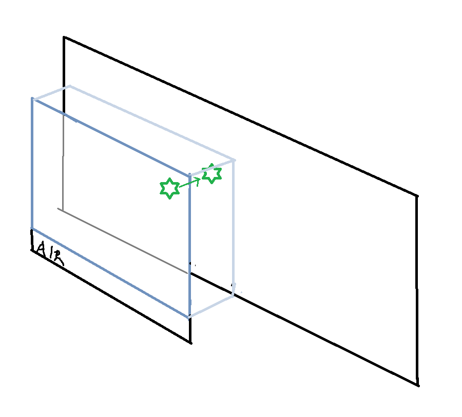
This means that if a sensor module is positioned above a display, with the black side facing outwards, and its TAA covering the screen - Both coordinates systems would be co-aligned and a reported touch would project on the display seamlessly. But if we were to flip the sensor module to cover the screen from underneath the display, a reported touch would appear to be reversed in y-direction since their coordinate systems would no longer be co-aligned, as the illustration show below.

Device Configuration List

Low- and High Bound
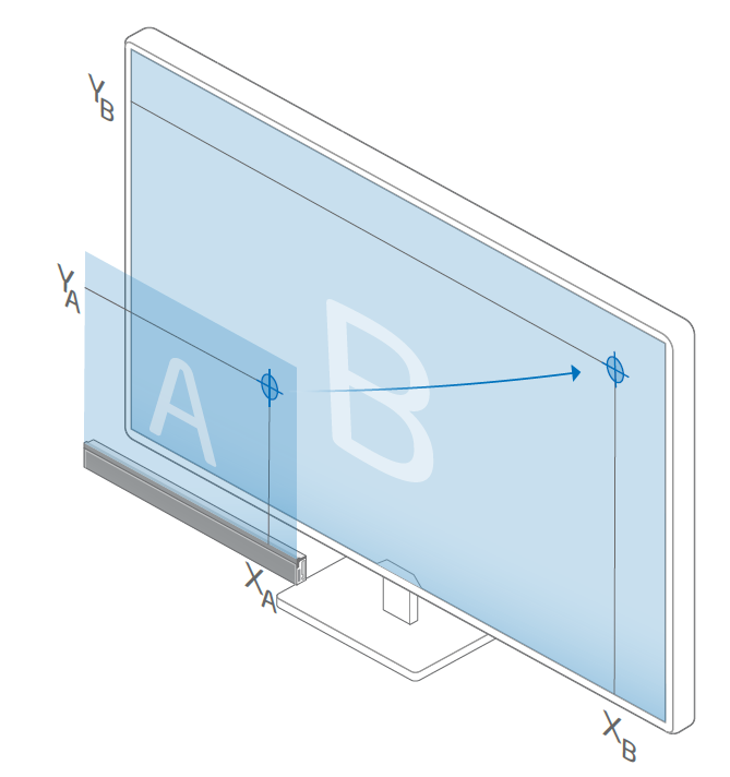
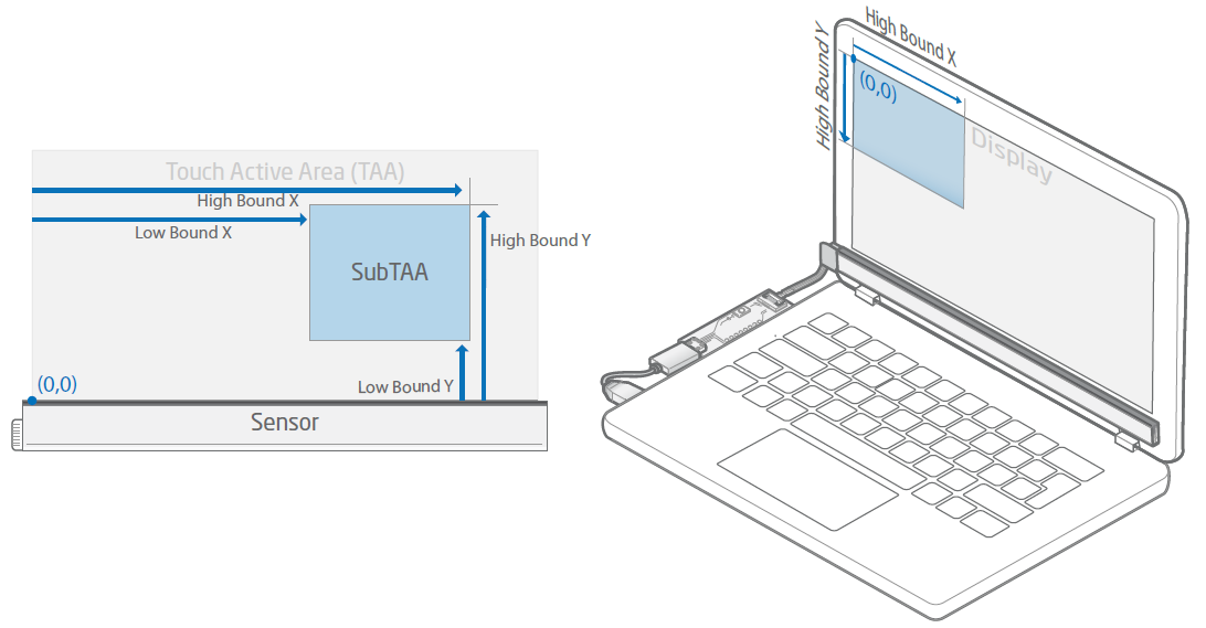
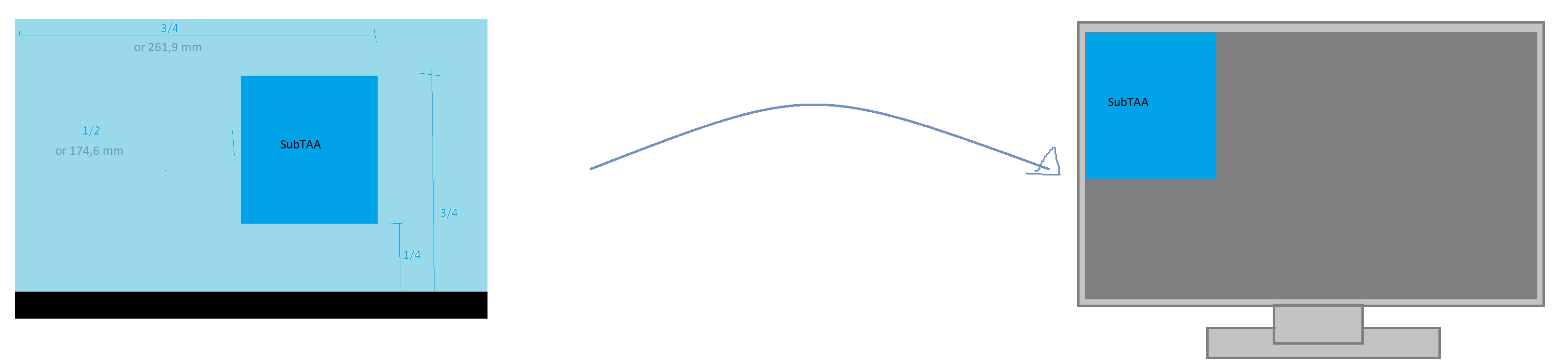
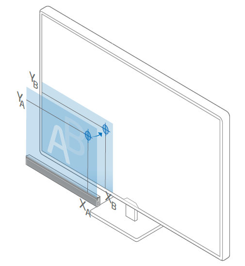
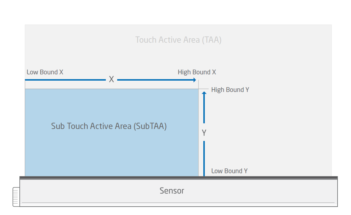
The Low or High Bound of the x- or y-axis can be configured in order to make a Touch Active Area (TAA) smaller, creating a so-called Sub Touch Active Area (SubTAA). This limits the interactive area, and touches would only be reported within the SubTAA.
The SubTAA is measured from its origin, in the range of Low Bound and High Bound, in x- or y-direction.

Where,
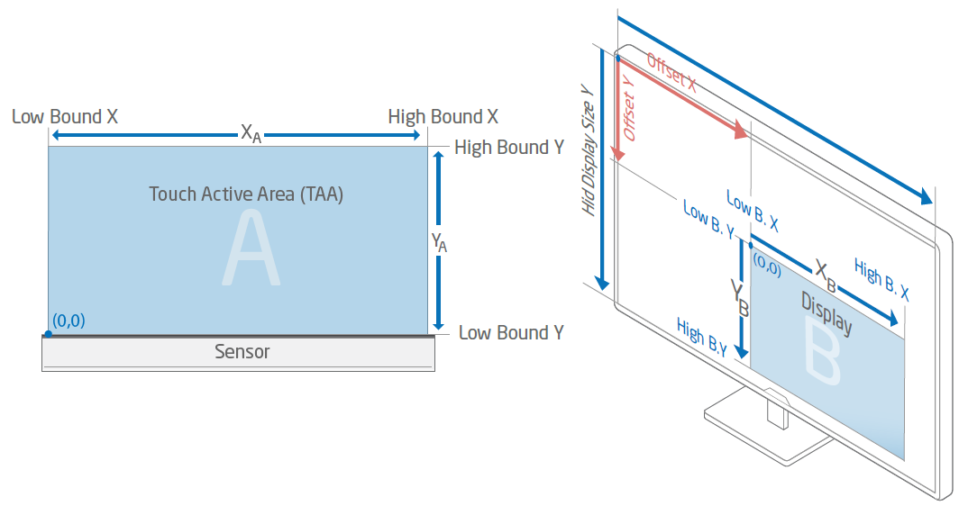
- Low Bound X - Start position of the (Sub)TAA in x-direction, measured from the origin of the TAA.
- High Bound X - End position of the (Sub)TAA in x-direction, measured from the origin of the TAA.
- Low Bound Y - Start position of the (Sub)TAA in y-direction, measured from the origin of the TAA.
- High Bound Y - End position of the (Sub)TAA in y-direction, measured from the origin of the TAA.
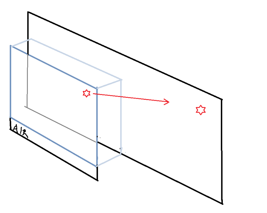
When projecting a SubTAA to a display within the host system, the projected SubTAA would then be mapped to the display's origin, regardless of its position (as shown in the illustration below).


Reverse X and Y
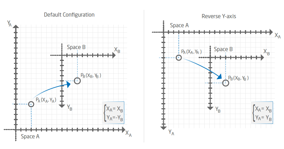
Reverse X or Y reverses the coordinates of a reported touch in x- or y-direction, without effecting the orientation of the (Sub) Touch Active Area. When positioning a sensor module, the axes of the Touch Active Area should either be positioned in the same orientation as the display, or have the reported touch coordinates adjusted. Please consider the following example.

Flip XY
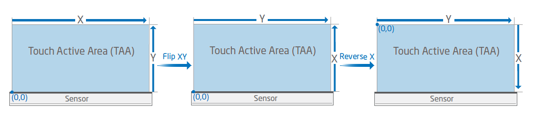
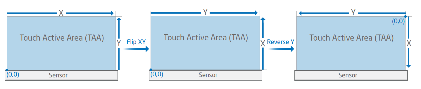
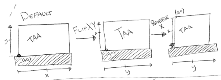
Flip XY swaps the x- with the y-axis of the reported touches, without effecting the orientation of the (Sub) Touch Active Area. When swapping axes, the reported touch data would then be sent to the host system containing the new x- and y coordinates.
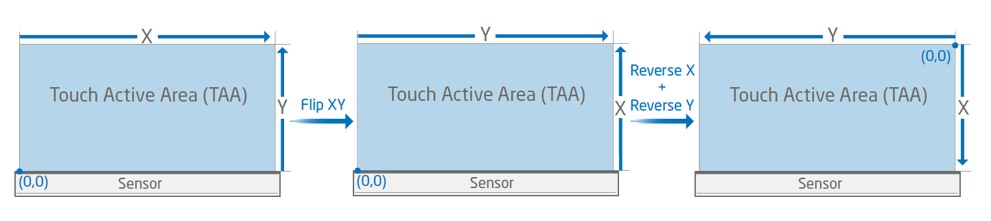
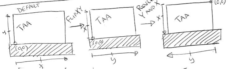
FlipXY together with ReverseX/Y can be used together which allows the Touch Sensor Module to be positioned around all edges of a display. When positioning a sensor module, the axes of the Touch Active Area should either be positioned in the same orientation as the display, or have the reported touch coordinates adjusted. Please consider the following example.

Offset X and Y
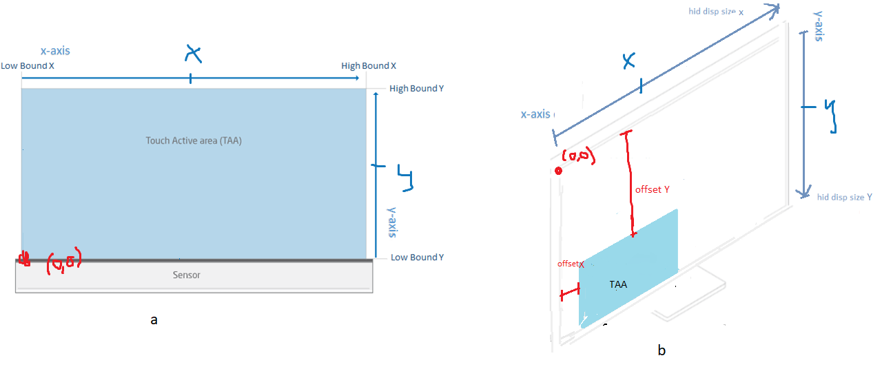
Offset X or Y configures the position of the mapped (Sub) Touch Active Area onto the display for the given axes. When adding the offset to a SubTAA, the position of the projected SubTAA will then be moved according to the following illustration.

Hid Display Size X and Y
Hid Display Size X or Y represent the width and height of a display in the host system. The default value is set to match the size of the sensor module's Touch Active Area, creating a proportional mapping regardless of the display size. In practice, this means that if a display is larger than the TAA, a projected touch would by default on the display proportionally, as if the projected TAA were "stretched" to fit the display size and ratio. An alternative to a proportional mapping would be to create an selective touch area, where only a part of the display have touch functionality.
Proportional Mapping
When Hid Display Size is set to the size of the Touch Active Area, the mapping of a reported touch would get projected proportionally, to fit the size of the display.
For instance, if a display within the host system is larger than the TAA, a reported touch will get projected as the illustration show below.

Selective Touch Area
It is possible to create a so-called Selective Touch Area, where only a part of the display have touch functionality.
For instance, if a Touch Sensor Module is positioned over a larger display, we can create a touch surface over that specific part of the screen. Please refer to Selective Touch Area for further information and examples.
