
Customer Documentation: Neonode® Touch Sensor Module User's Guide : .Sub Touch Active Area and Device Configuration v1.8
The zForce AIR Touch Sensors have a set of settings called Device Configuration that can be accessed and managed by the end user. Device Configuration creates the ability to configure the number of reported touches, touch frequency, mapping of the reported touch, and defining a Sub Touch Active Area (SubTAA). These settings are implemented in the ASN.1 protocol, which means that the device configurations can be accessed and implemented through Workbench or zForce Example SDK.
Index
Mapping
The mapping between these two spaces can be customized by using Device Configuration, which makes for a wider range mounting and implementation possibilities. By having Operation Mode set to Detection Hid allows the user to position their zForce AIR Touch Sensor's Touch Active Area (TAA) over a display to achieve touch functionality, where the TAA is the maximum area of which touches can be reported.
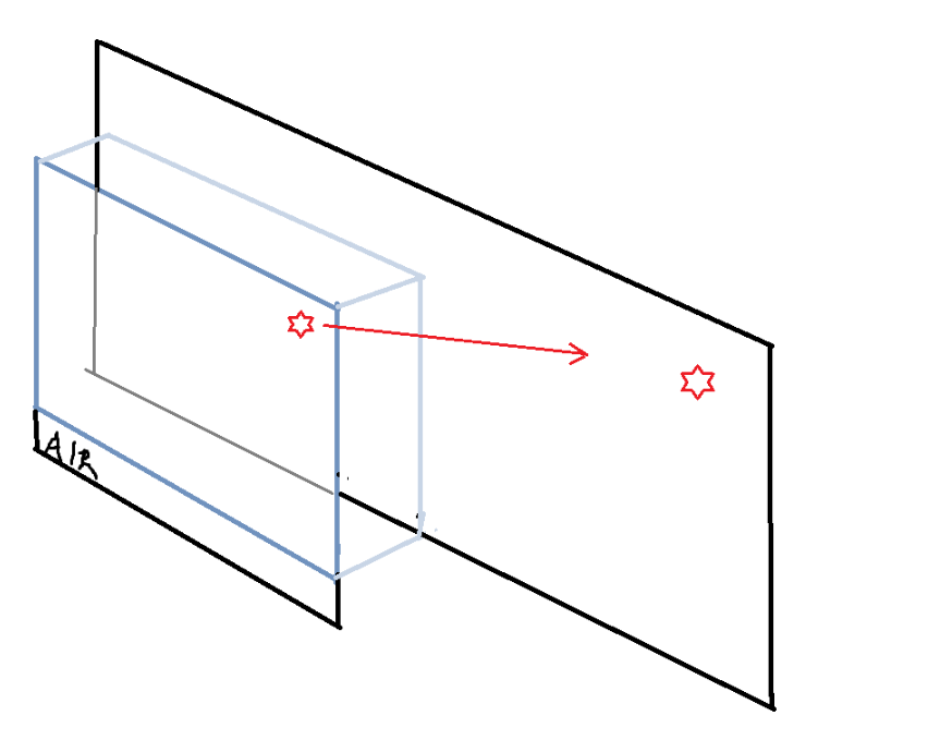
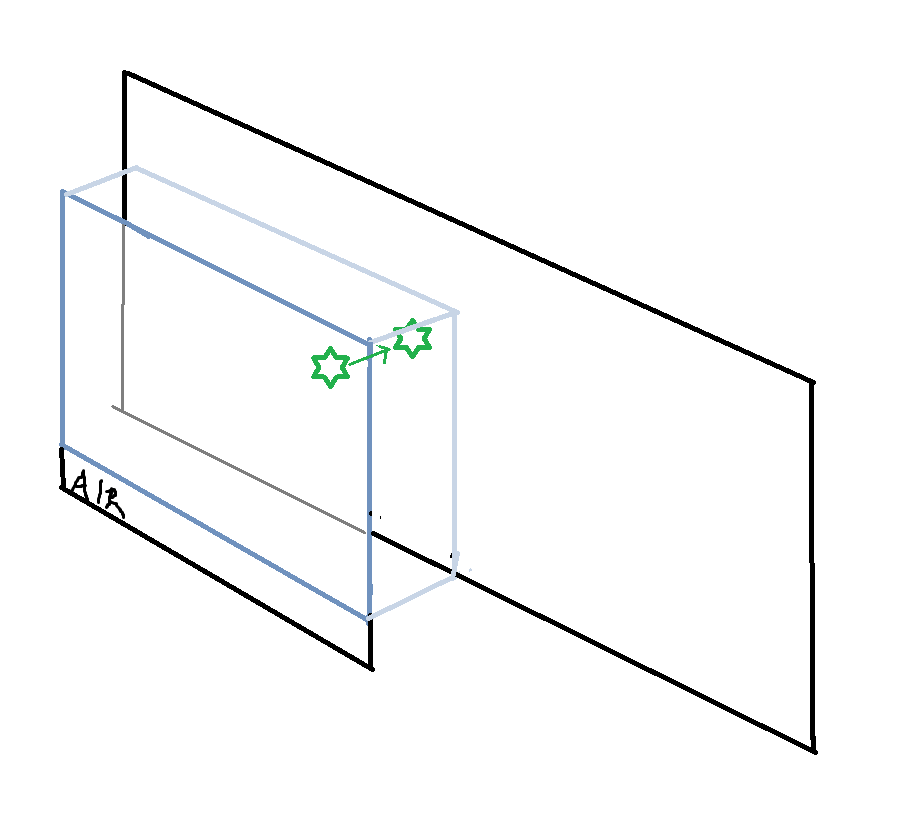
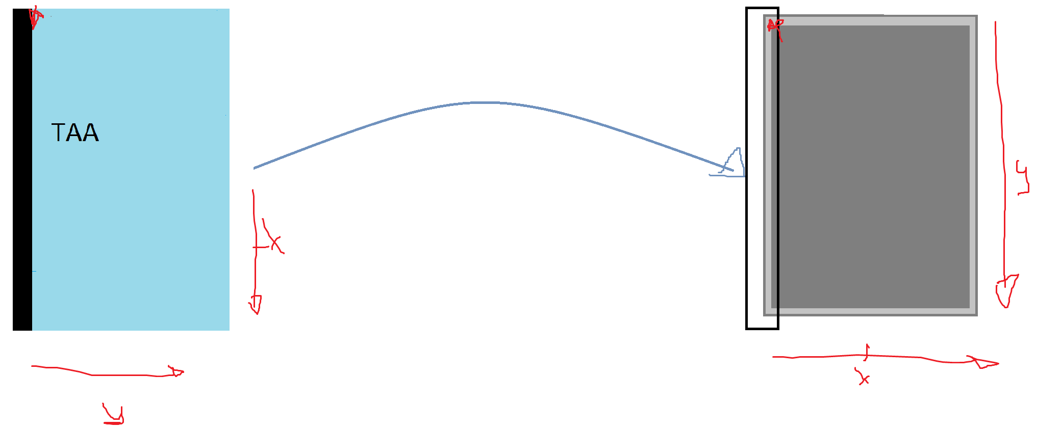
Whenever a touch is being reported, the position coordinates (xA, yA) gets transformed and mapped from the TAA (space "A") onto the display in the host system (space "B"). The transformation of the coordinates (x,y) mapps with respect to the Device Configuration. In order to get a true 1:1 mapping as in Figure 2, both spaces must be considered in to get the preferred scaling and position of the mapped coordinates. By having the x-axes and y-axes of both spaces facing the same directions, the reported touches are mapped to the display in the right position.
If the x- and y-axes of space A and B are not sharing the same direction, the position of the reported touches would appear to be reversed. This can be configured by using the the configuration Reverse X, Reverse Y or Flip XY (Covered in section Reverse X/ Reverse Y and FlipXY).
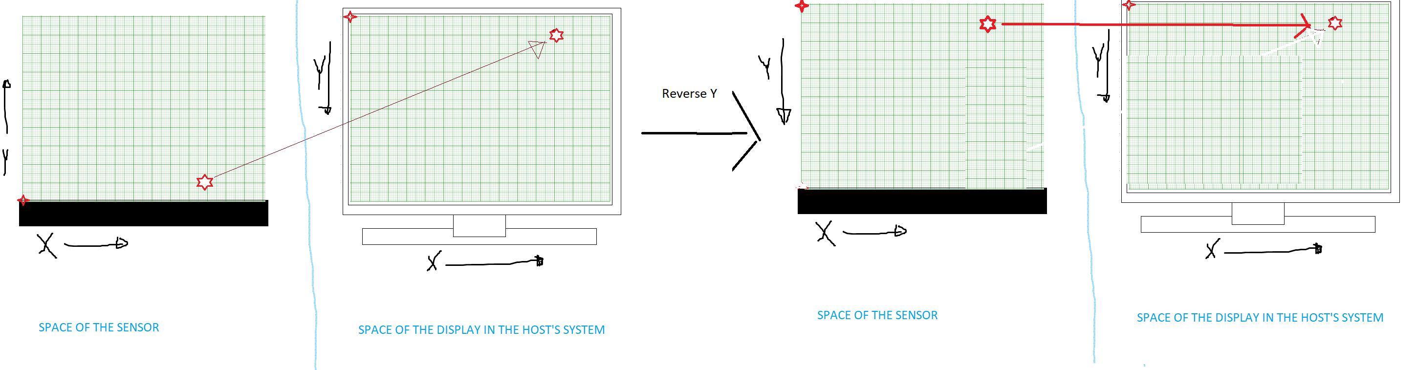
The origin is by default positioned at the bottom left corner of the TAA (Figure 4a), while origin is positioned at the upper left corner of the display (Figure 4b). If the sensor were mounted under a display as in Figure 2, the y-axis would appear to be reversed since the origins are not stationed in the same position. This can be solved by configuring the variable Reverse Y.

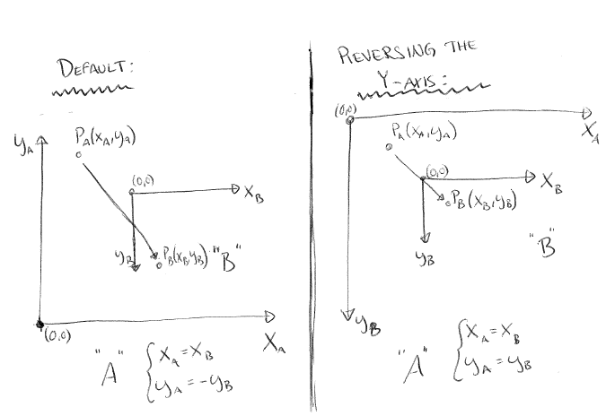
Figure 1 - Mapping the point PA(xA, yA) to PB(xB, yB) from the space A→B, where A is the space of the TAA, and B is the space of the display.
-Default: The sensor(space A) is positioned alongside with the x-axis with the TAA facing the positive side of the y-axis. The display is positioned to face the viewer. This mapping results with a reversed y-axis.
-Reversing Y-axis: The sensor(space A) is positioned alongside with the x-axis with the TAA facing the positive side of the y-axis. The display is positioned to face the viewer. This transformation results as a true corresponding mapping.

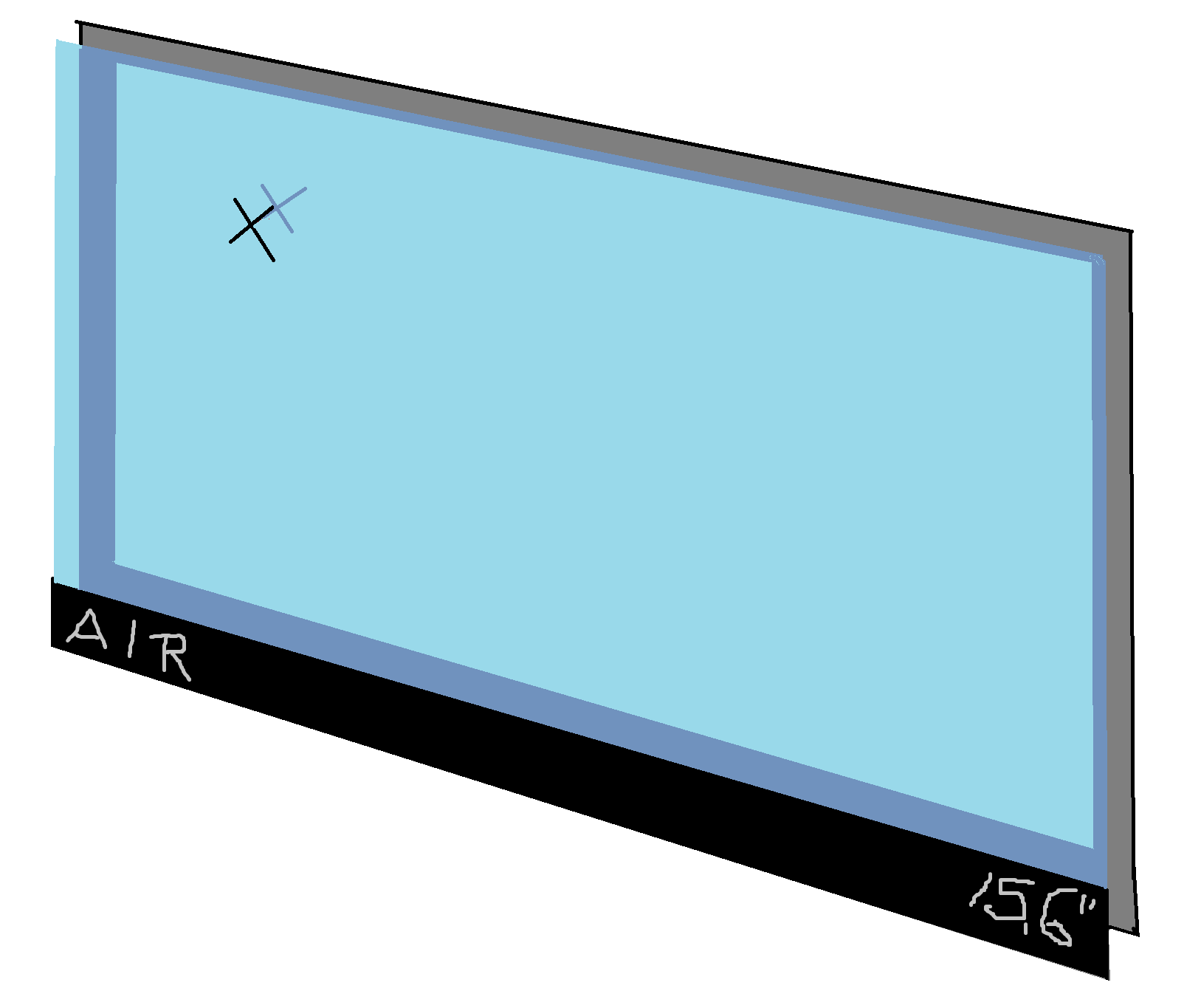
Figure 2 - 1:1 True mapping illustration of a zForce AIR Touch Sensor in front of a screen, where "x" marks the position of a reported touch on the TAA, and the mapped position on the screen.
Example 1
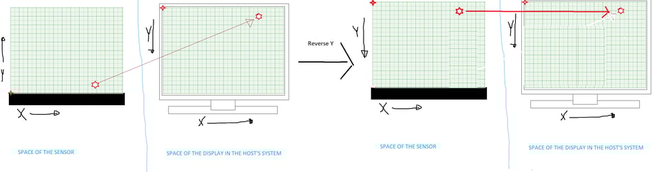
Figure 3 - Illustration of Example 1
Consider placing a zForce AIR Touch Sensor with default configuration under a laptop display. Hence, the sensor's coordinate system have the origin stationed at the bottom left corner, and the host's coordinate system of the display have the origin stationed at the upper left corner, the y-coordinate would appear to be reversed. In order to get a correct corresponding mapping, the y-axis needs to be reversed (Ref. to section Reverse).
Configuration List
*Thus, this accepted range in is only due to software limitations, each device have their own physical hardware limitation that needs to be considered. You can find the hardware limitations in each device and firmware update in Mechanical Data

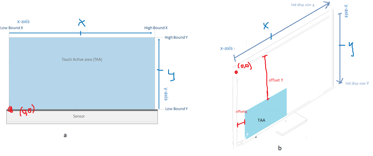
Figure 4 -
a, zForce AIR Touch Sensor View: Configuration Variables that affects the space of the Sensor
b, Configuration Variables that affect the space of the host's system.
Low Bound / High Bound
The TAA is defined by the x- and y-range, which can be configured by changing its size and position, where the ranges are set to the size of the TAA by default. The x- and y-ranges are the space in between Low- and High Bounds of x and y. Low- and High Bound X mark the start and endpoint of the x-range, while Low- and High Bound Y marks the start and endpoint of the y-range.
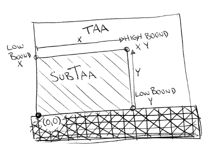
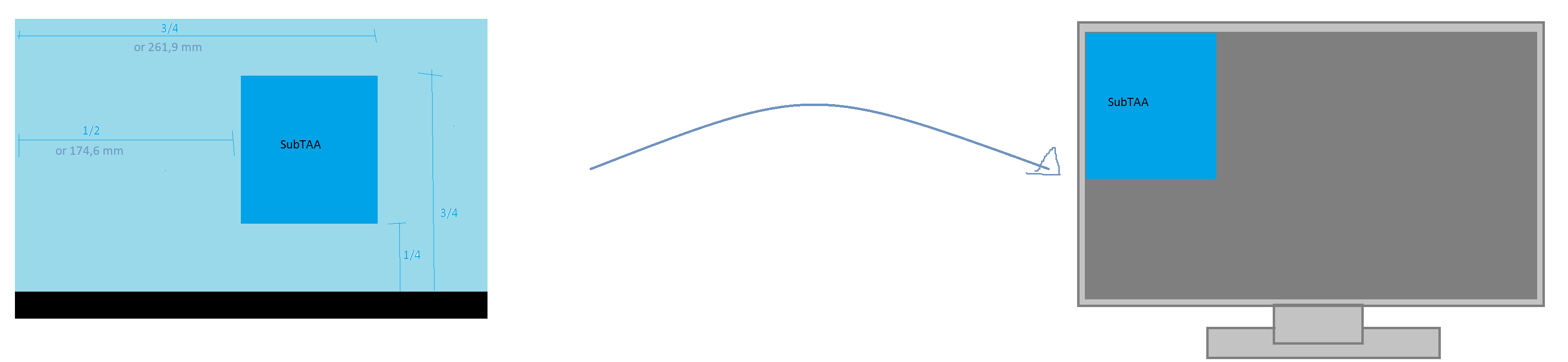
Figure 5 - A SubTAA created from the interval of Low-/HighBoundX and Low-/HighBoundY
The coordinates of Low Bound X and Low Bound Y are mapped to the position of the origin of the display. By making configuring to Low- /High Bound, a so-called Sub Touch Active Area (SubTAA) will be generated from the area limited by the new x- and y-range. A SubTAA would be positioned so that Low Bound of x and y were positioned at the origin of the display, as shown in Figure 5. In order to place the mapped SubTAA in the same position as the TAA, an Offset needs be set in order to change the position of the area (Covered in section Offset).
The coordinates (x, y) of a reported touch is measured from the origin that is stationed at the bottom left corner of the TAA, and maps onto the host system (display) that have the origin is placed on the upper left corner of the screen (covered in section Mapping).
Example 2

Figure 6 - Illustration of a SubTAA and its mapped position
Consider creating a SubTAA by positioning a 340 zForce AIR Touch Sensor with default configuration under a 15" display. In order to create the SubTAA according to Figure 6, the following adjustments needs to be made.
Reverse X/ Reverse Y
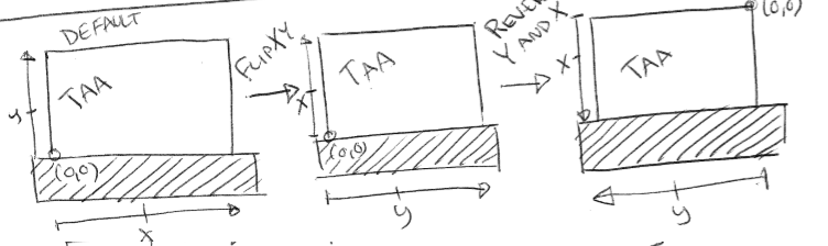
Reverse X or Reverse Y changes the direction of the axis in question within the space of the TAA. Reverse together with Flip XY (Ref. to section FlipXY) creates the ability to position the sensor around all edges of a rectangular display that's rotated in any direction.
Example 3
Consider mounting a zForce AIR Touch Sensor under a display, as in Figure 2. If a touch would be reported close to Low Bound Y, the reported touch would be mapped onto the top of the display (as in Figure 3). This indicates that the origins of the display and the TAA are not stationed correspondingly. Hence, the sensor's coordinate system have origin placed at the bottom left corner, and the display have origin placed in the upper left corner. The y-axis would appear to be reversed. By having Reverse Y set to True, the origin will change position so that the TAA share the same corresponding position as the display.
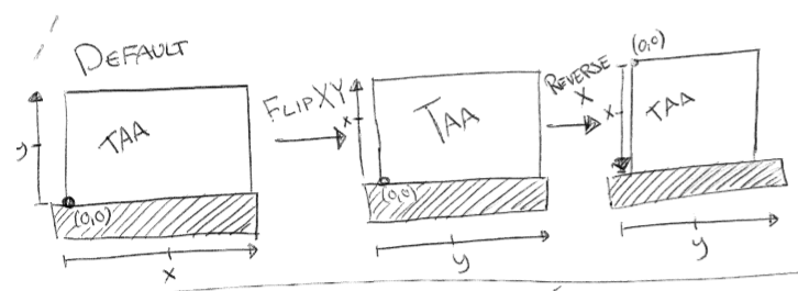
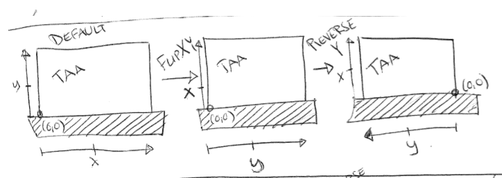
Flip XY and Using Multiple Transformations
Flip XY Swaps the x-axis with the y-axis in respect of the axes default direction within the space of the TAA. Flip XY together with Reverse creates the ability to position the sensor around all edges of a rectangular display that's rotated in any direction.
By letting FlipXY and ReverseX/ReverseY be set to True, the FlipXY transformation would apply before the Reverse transformation, as such.
Other transformations such as Offset are not affected by Flip XY nor Reverse. Since Offset changes the position of the coordinates as if the axes were moved on the display. The transformations FlipXY, Reverse, and Low-/High Bound take affect in the space of the TAA, while Offset and Hid Display Size take affect within the space of the hosts system (or display). Thus, they will not interact nor affect each other.
Example 4
 Figure 10 - Illustration of example 4
Consider having a zForce AIR sensor mounted on the left hand side of a screen where the TAA is covering the whole screen. Assume that the TAA and the display have the same size. Since the sensor's and screen's coordinate systems shares the same position of origin, no axes needs to be reversed. Even though the origin is stationed at the correct position, the axes need to be switched since the x- and y-axes of the TAA are in the opposite position with respect to the screens coordinate system.
Offset X / Offset Y
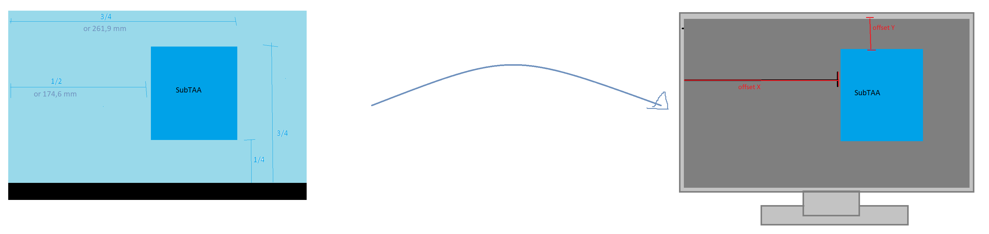
Offset configures the position of the x- and y-axes in the space of the host's system (or display). By shifting the axes, the position of the reported touch will be moved with respect to the value of the offset. The position of Low- and High Bound X and Y would also get shifted and move a SubTAA correspondingly.
Example 5

Figure 11 - Illustration of example 5
Consider Example 2 and the created SubTAA. In order to change the mapped position of the SubTAA to match its position in the TAA, the coordinates on the host's display must me shifted. This adjustment is done with Offset, as such.
Hid Display Size X / Hid Display Size Y
Hid Display Size defines the length of the x- and y-axes on the host system where x represents the height, and y represents the width of the host's display. Having the ability to customize the display’s size allows the end user to make further customizations in form of the mapping ratio. A reported touch can for instance be mapped onto a screen that is larger than the TAA.
Consider a display that is larger than the TAA. By setting Hid Display Size to the same values as the TAA will give the effect of having the x- and y-axes scaled match the screen proportions. This concludes that if a touch would be reported at the right hand side of the TAA, the interaction would appear on the right hand side of the screen with the same mapping proportions as the sensor (Refer to Table Configuration Example nr.2)