
Customer Documentation: Neonode® Touch Sensor Module User's Guide : .Selective Area Touch v1.6
Use Case
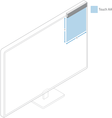
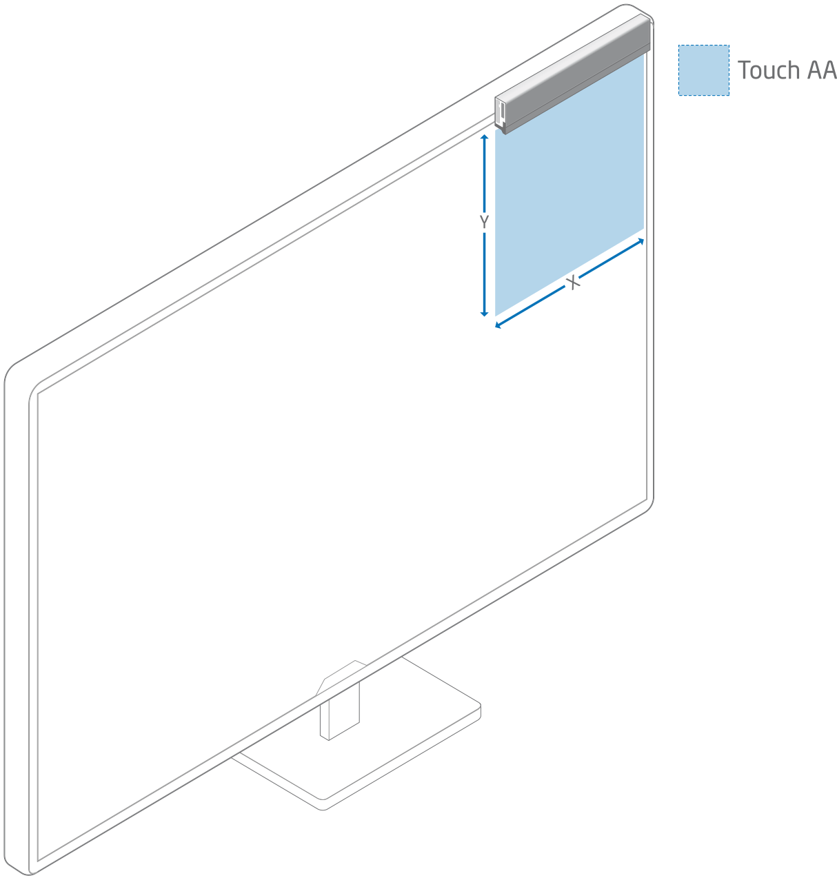
This method of configuring sensor(s) can be used to get one or multiple touch areas on a larger screen or on a large projected area, further referred to as Screen.
Illustrations
Introduction
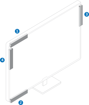
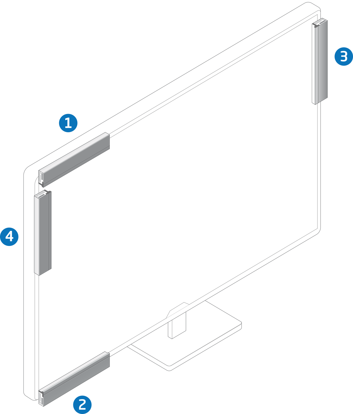
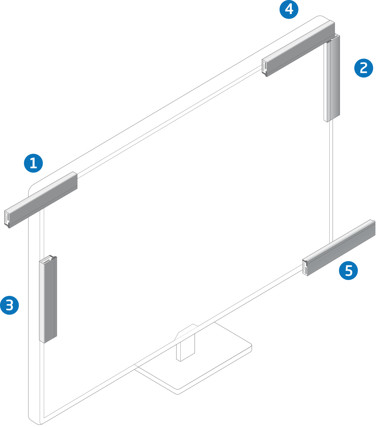
A sensor can be mounted on four sides of a screen and with the connector to either the right or the left (PCB or silver side down) but we recommend mounting it with the silver side towards the screen, as the touch area is then closer to the screen.
This will give a total of eight different configurations.
It is possible to mount a sensor "on" or "in" the screen. However this will cover/block part of the screen and is therefore not a part of this example.
- Top: Sensor on top of the screen facing down.
- Bottom: Sensor on bottom of the screen facing up.
- Right: Sensor on right side of the screen facing left.
- Left: Sensor on the left side of the screen facing right.
HID Display Size
HID Display Size is the physical size of the screen in tenths of millimeters (1/10 ; 1 mm = 10)
Configurations With One Sensor
NOTE: Values in bold has to be changed from default to make the configuration work.
Configurations With Multiple Sensors
If you would like to configure multiple sensors for touch on different parts of the screen, please use the settings above for each sensor. If you would like to make this setting with Neonode Workbench, please use the Workspace designated for multiple sensors. If you would like to create your own solution, the zForce SDK can be used to implement this.