
Customer Documentation: Neonode® Touch Sensor Module User's Guide : .Parameter Overview v2.5
Index
Introduction
This page describes the parameters currently available in the Touch Sensor Module Firmware 1.55 and Neonode Touch Sensor Module Firmware (NTSMF 2.0-BETA), except for Scanning Range which is only available in NTSMF 2.0-BETA through zForce Programmer.
The parameters described in this document can be adjusted by changing the Touch Sensor Modules configuration. These parameters can be configured using Neonode Workbench, an application using zForce SDK, Arduino Library (I2C) or zForce Programmer. The parameters that have been configured using either Neonode Workbench, zForce SDK or Arduino Library, are stored in the RAM memory, meaning that the new configuration will have to be re-applied after each reboot. If the parameters are instead configured using zForce Programmer, the parameters will not have to be re-applied after each reboot.
Scanning Range
This setting is only available through zForce Programmer. Modifying the scanning range can be useful when the range has to be extended on longer touch sensor modules (346, 330, and 310) and also offers the possibility to set a shorter scanning range. This differs from setting the touch active area Max Y setting as it modifies the actual scanning range of the sensor. If only the Max Y setting would be used, it would still be able to see touches outside of the touch active area, but it would invalidate them and not report them as touches.
Touch Active Area Adjustments
Axis Orientation
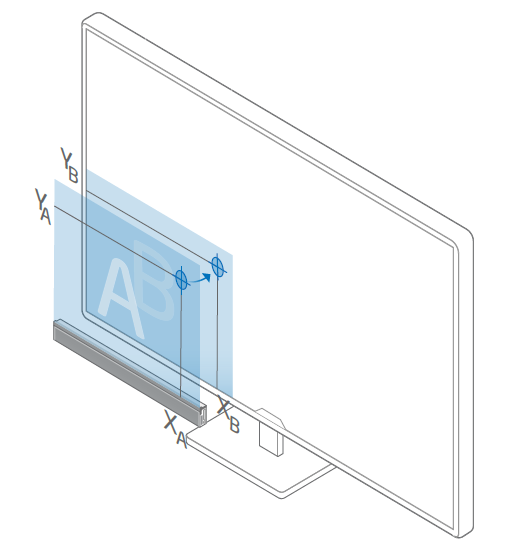
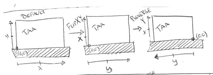
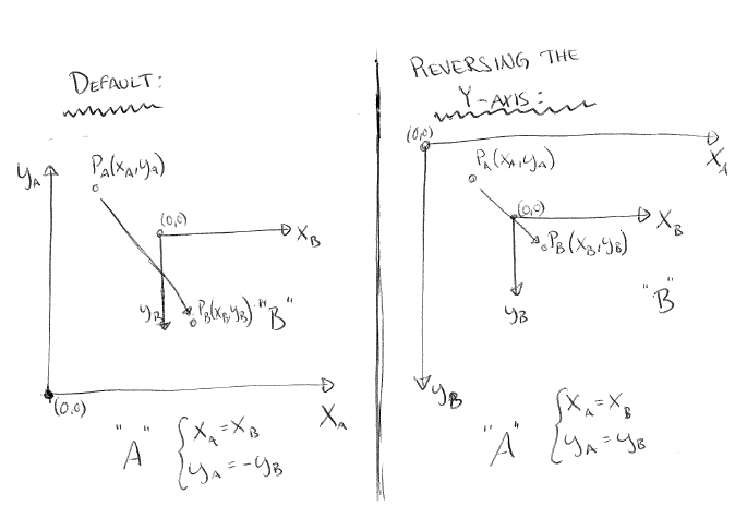
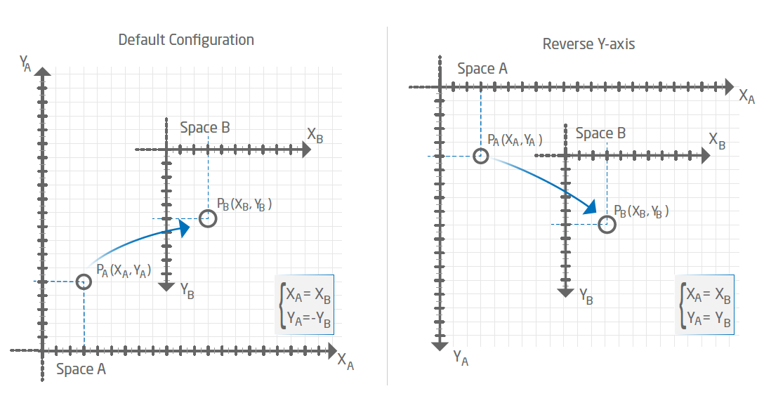
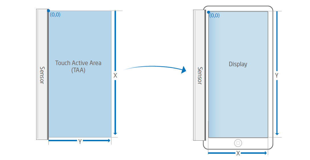
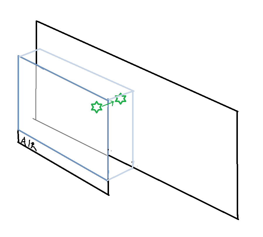
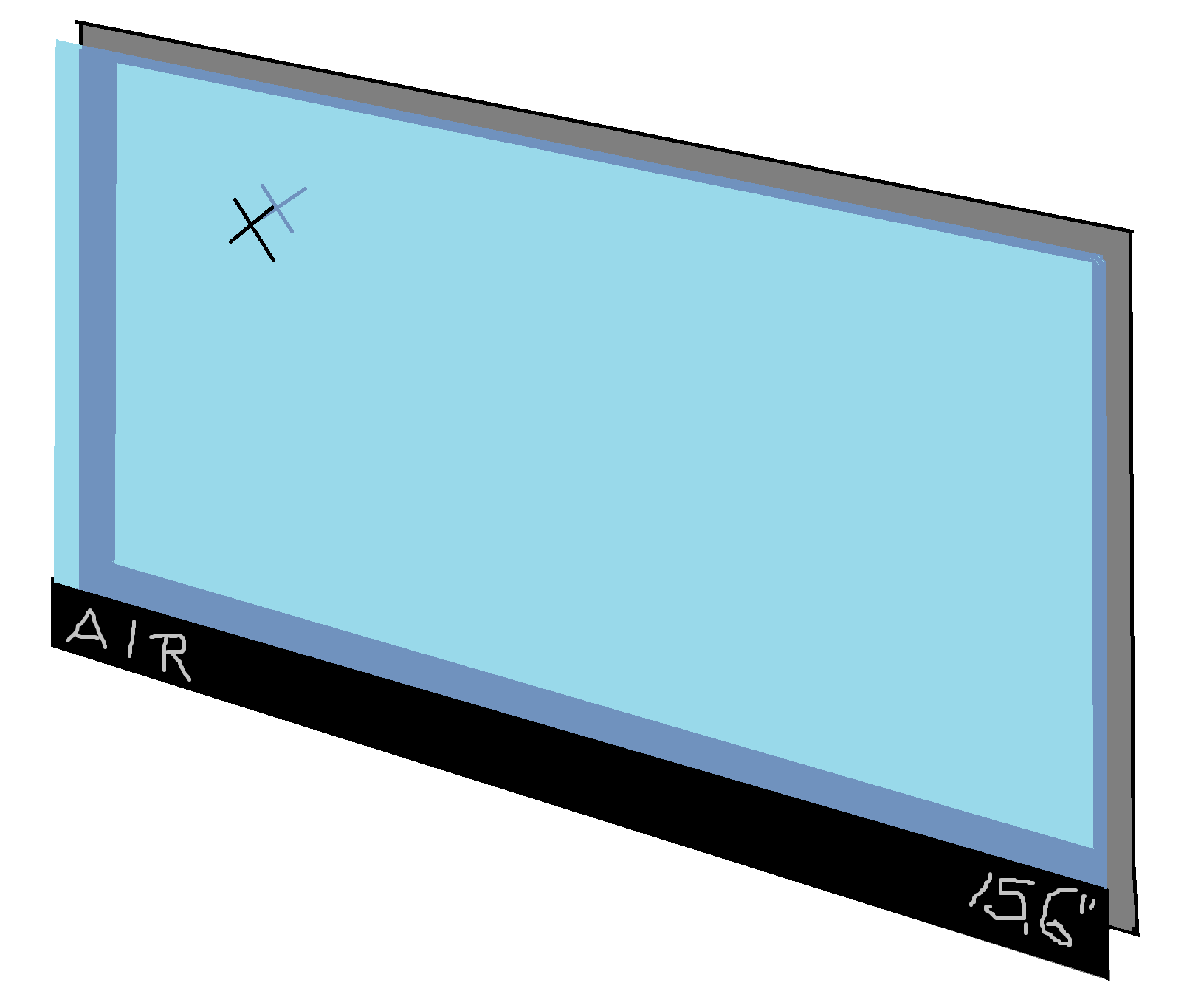
When mapping a reported touch from the Touch Active Area to a display, it is important that the orientation of the TAA, as well as the display are taken into account. When positioning a Touch Sensor Module over a display to achieve touch functionality, both systems needs to be co-aligned in order for a reported touch to be projected in the same corresponding position of the screen. If both systems are not oriented in the same way, the reported touches are going to be reversed depending of the setup. Luckily, the orientation of the reported touches can be configured to counter this by using ReverseX/ReverseY or FlipXY in Device Configuration. These settings rotates or flips the given coordinates of the reported touches, which allows the Touch Sensor Module to be mounted at any of the 4 sides of the screen
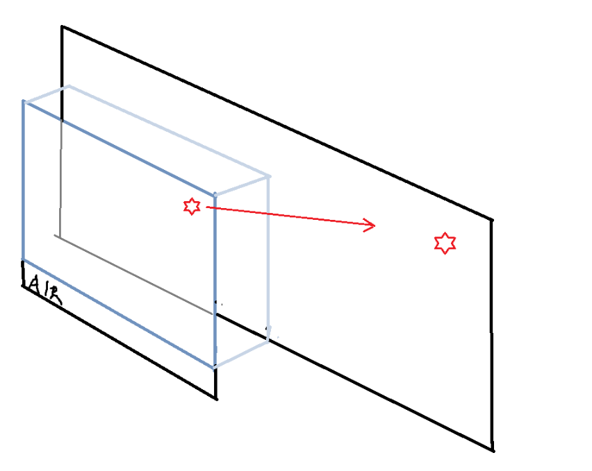
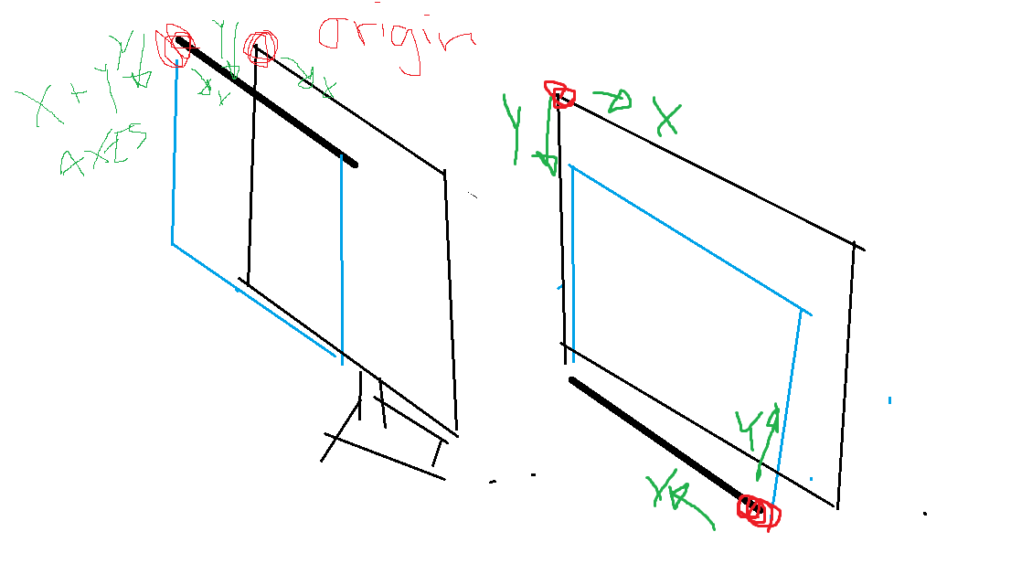
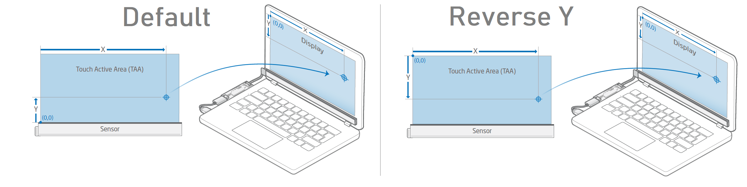
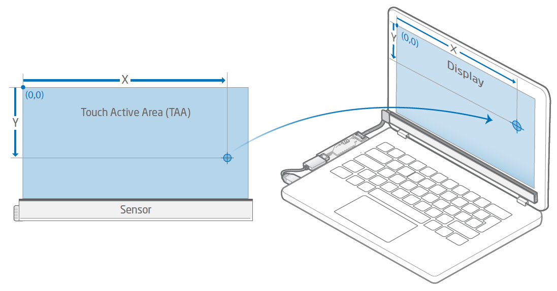
Almost all displays have a reference point (or origin) positioned at the upper left corner of the screen, where the x-axis points in the direction to the right, with the y-axis pointing downwards. The origin of the Touch Sensor Module's Touch Active Area is positioned on the left hand side, when having the TAA facing downwards, with the black side of the Touch Sensor Module facing outwards.
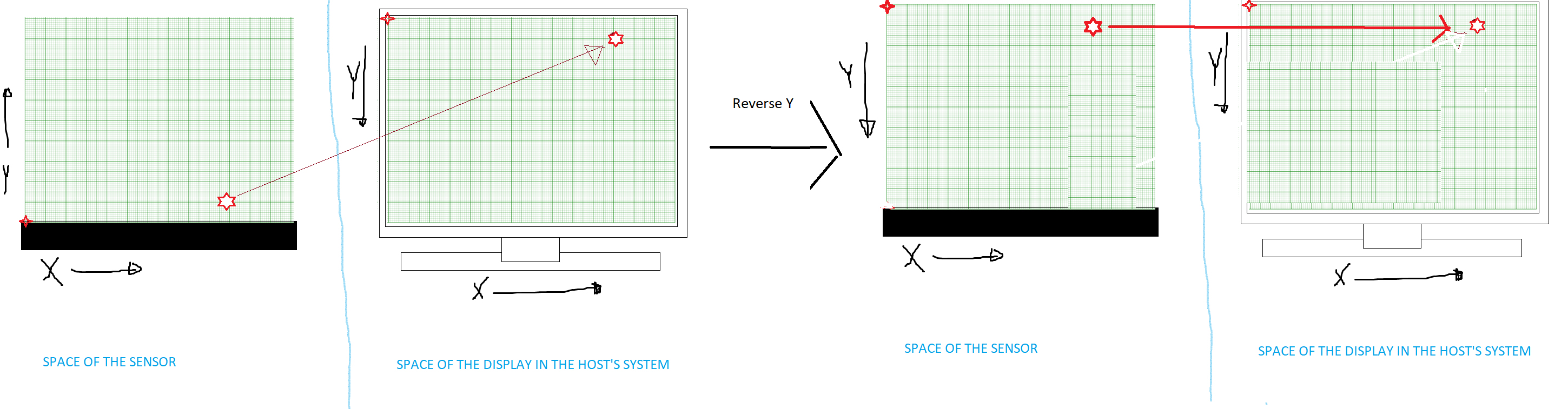
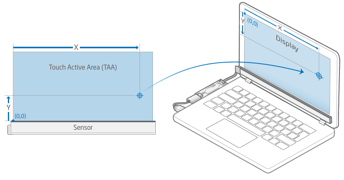
This means that if a Touch Sensor Module is positioned above a display, with the black side facing outwards, and its TAA covering the screen - both coordinates systems would be co-aligned and a reported touch would project on the display seamlessly. But if we were to flip the Touch Sensor Module to cover the screen from underneath the display, a reported touch would appear to be reversed in y-direction since their coordinate systems would no longer be co-aligned, as illustrated below.

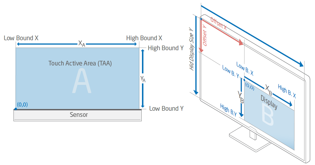
Touch Active Area Size
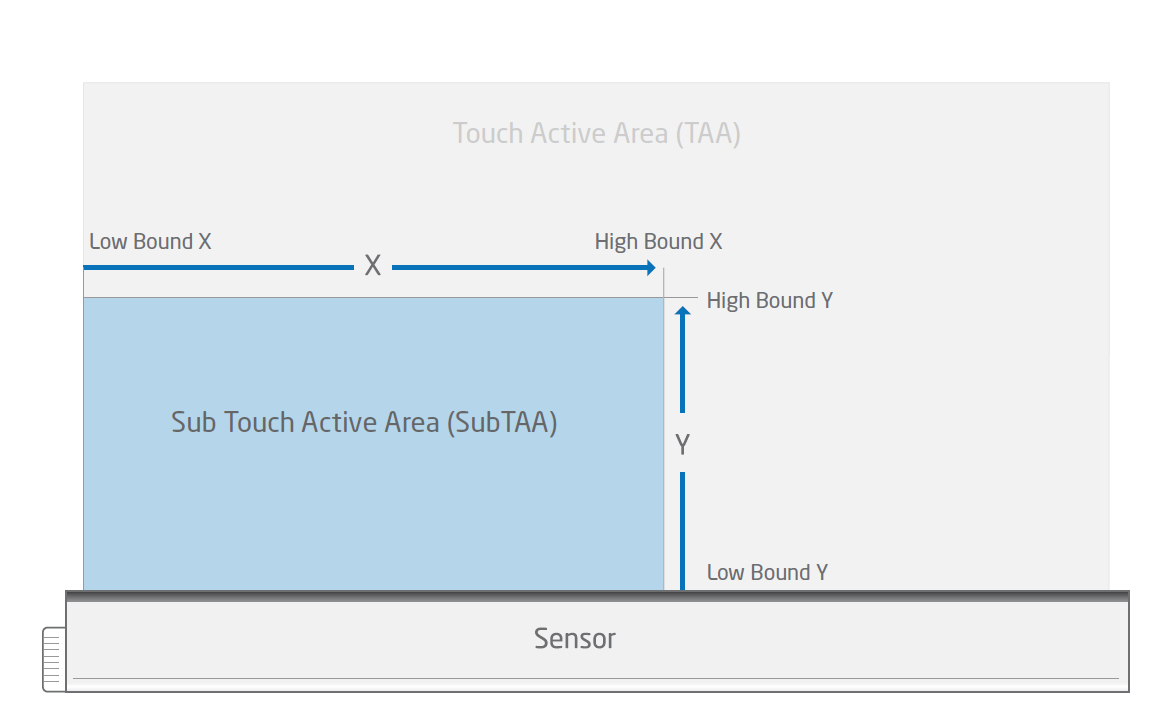
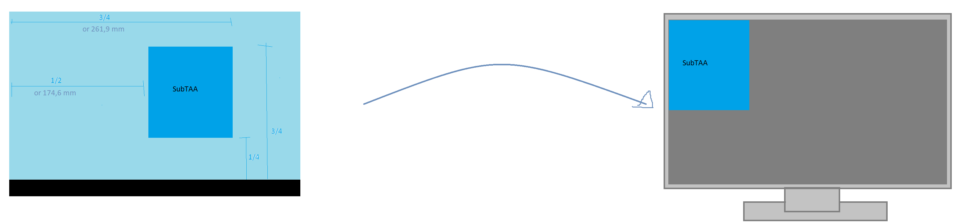
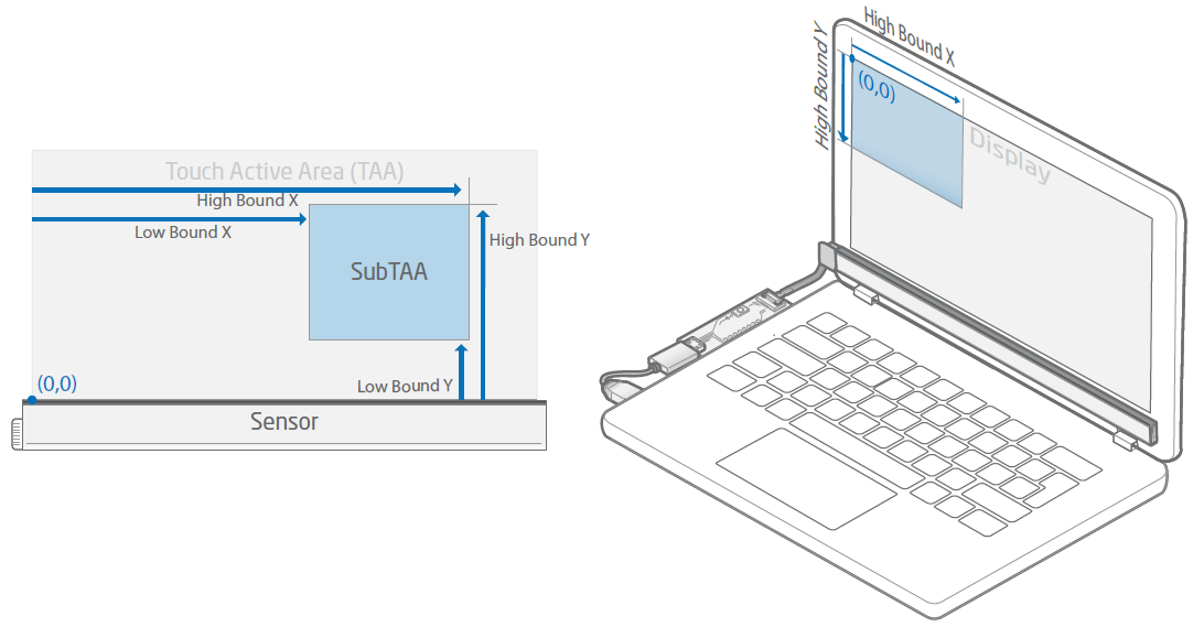
The Low or High Bound of the x- or y-axis can be configured in order to make a Touch Active Area (TAA) smaller, creating a so-called Sub Touch Active Area (SubTAA). This limits the interactive area, and touches would only be reported within the SubTAA.
The SubTAA is measured from its origin, in the range of Low Bound and High Bound, in x- or y-direction.

Where,
- Low Bound X - Start position of the (Sub)TAA in x-direction, measured from the origin of the TAA.
- High Bound X - End position of the (Sub)TAA in x-direction, measured from the origin of the TAA.
- Low Bound Y - Start position of the (Sub)TAA in y-direction, measured from the origin of the TAA.
- High Bound Y - End position of the (Sub)TAA in y-direction, measured from the origin of the TAA.
When projecting a SubTAA to a display within the host system, the projected SubTAA would then be mapped to the display's origin, regardless of its position (as shown in the illustration below).


Reverse X and Y
Reverse X or Y reverses the coordinates of a reported touch in x- or y-direction, without effecting the orientation of the (Sub) Touch Active Area. When positioning a Touch Sensor Module, the axes of the Touch Active Area should either be positioned in the same orientation as the display, or have the reported touch coordinates adjusted. Please consider the following example.

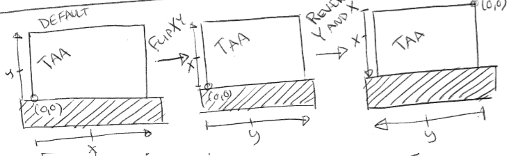
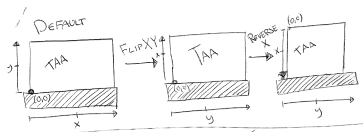
Flip XY
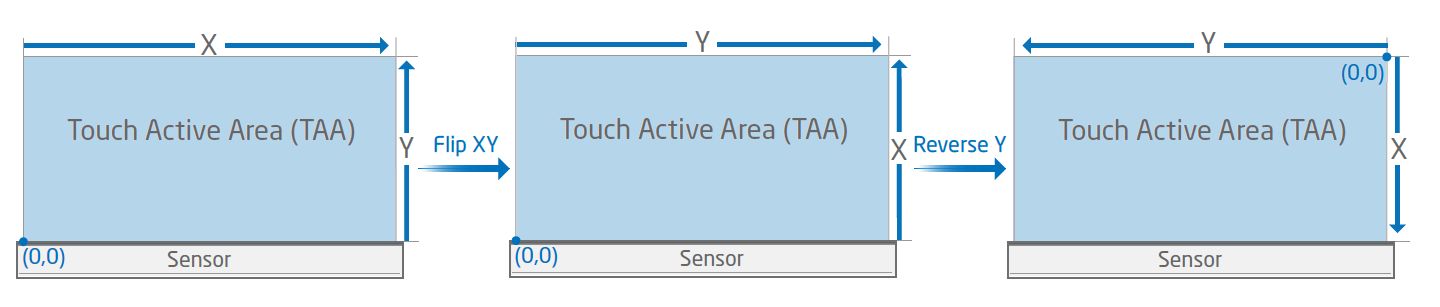
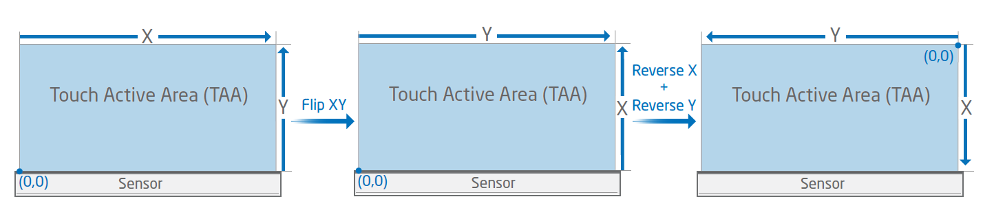
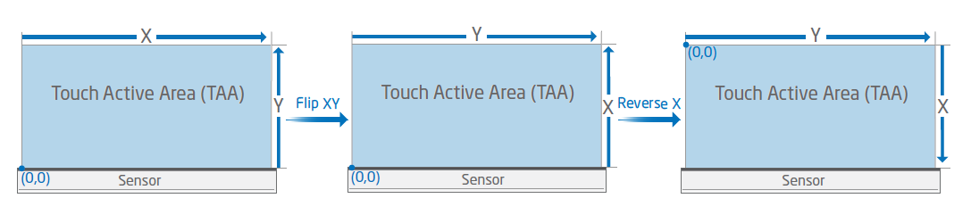
Flip XY swaps the x- with the y-axis of the reported touches, without effecting the orientation of the (Sub) Touch Active Area. When swapping axes, the reported touch data would then be sent to the host system containing the new x- and y coordinates.
FlipXY together with ReverseX/Y can be used together which allows the Touch Sensor Module to be positioned around all edges of a display. When positioning a Touch Sensor Module, the axes of the Touch Active Area should either be positioned in the same orientation as the display, or have the reported touch coordinates adjusted. Please consider the following example.

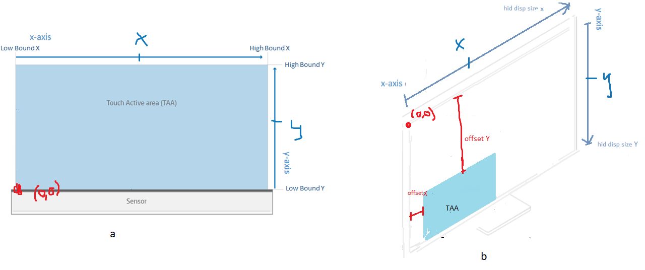
Offset X and Y
Offset X or Y configures the position of the mapped (Sub) Touch Active Area onto the display for the given axes. When adding the offset to a SubTAA, the position of the projected SubTAA will then be moved according to the following illustration.

Hid Display Size X and Y
Hid Display Size X or Y represent the width and height of a display in the host system. Hid Display Size is used to scale the reported touches onto the display. The default Hid Display Size values are set to match the size of the Touch Sensor Module's Touch Active Area, creating a proportional mapping regardless of the display size.
Proportional Mapping
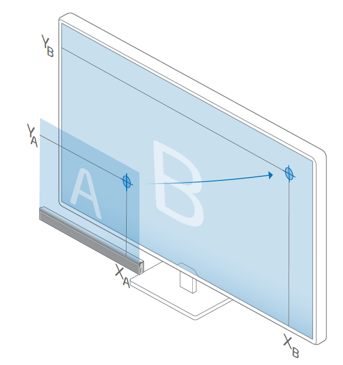
When Hid Display Size is set to the size of the Touch Active Area, the mapping of a reported touch would get projected proportionally, to fit the size of the display.
For instance, if a display within the host system is larger than the TAA, a reported touch will get projected according to the illustration below.

Selective Touch Area
It is possible to create a so-called Selective Touch Area, where only a part of the display have touch functionality.
For instance, if a Touch Sensor Module is positioned over a larger display, we can create a touch surface over that specific part of the screen. Please refer to Selective Touch Area for further information and examples.

Object Size Restrictions
Only reports touches with an object size that is within the defined limits.
Click On Touch
The click on touch parameters gives the option to make the Touch Sensor Module report a click event upon entering the touch field as opposed to report a click event when an object leaves the touch field. This is useful when using the Touch Sensor Module in a contactless touch implementation, and gives more rapid feedback to the user.
Click on Touch Enabled
Enables or disables click on touch.
Time to Up
Time from the down event until the up event is sent. Setting this to 0 completely disables the possibility to do swiping gestures (or drawing). Setting this to e.g 100ms gives the end user 100ms to move outside of the set Distance (described below) and begin the swipe gesture instead.
Distance
This value sets the minimum range that the touch object has to move before starting a swipe gesture.
Frequency Settings
The frequency parameters set the various scannning frequencies. The maximum scanning frequencies are depending on the product variant.
Finger Frequency
Activated when objects with characteristics matching regular fingers are detected.
Idle Frequency
Activated when no objects are detected in order to minimize power usage.
Floating Protection
The floating protection parameter gives the option to modify or disable one of the touch recognition filters that are available in the Touch Sensor Module.
Floating Protection Enabled
This is a Boolean value that completely disables or enables this filter.
Floating Protection Time
This value indicates how long this filter would need to validate the first reported touch. Default value is 40ms. With a lower value the risk increases that a false touch would be reported, and the opposite with a higher value.
Number of reported touches
The number of touches that can be reported simultaneously. For example, setting this to 5 will make the sensor report up to 5 simulatenous touches.
Reflective Edge Filter
This is a Boolean value to disable or enable the reflective edge filter. This filter is useful when there is a high risk that there will be a highly reflective materials right outside the Touch Active Area. In the presence of such materials there is a risk that the Touch Sensor Module will report it as a touch within Touch Active Area. An example of a highly reflective material could be a white paper or something similar.