
Customer Documentation: Neonode® Touch Sensor Module User's Guide : .Getting Started with Sensor Evaluation - SDK with USB v2.0
Required Equipment
The following equipment from the evaluation kit is required:
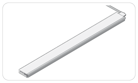
- 1 x zForce AIR Touch Sensor
- 1 x FPC cable with connector
- 1 x Interface board
Additional required equipment:
USB cable with a Micro USB type B connector
Make sure that the USB cable transmits both power and data and not only power.
- (Optional) tape for mounting.
Connecting Sensor
- Connect the FPC cable to the interface board:

- Lift the flip lock on the interface board.
Insert the FPC cable into the end of the connector, with the connector pads facing down, towards interface board. The yellow piece of PCB of the connector on the other side of the cable is facing upwards. Make sure the direction is straight into the connector and the pads have reached the end of the connector.
Make sure the connector pads of the FPC cable are facing downwards, towards interface board. The sensor risks damage if the FPC cable is connected in wrong direction.
Press down the flip lock.
- Connect the FPC cable to the sensor:

- Place the sensor so that the sensor connector pads of the sensor are facing downwards (steel surface upwards).
- Insert sensor into the connector on FPC cable (yellow piece of PCB of the FPC connector still facing upwards).
- Make sure the direction of the pads is straight into the connector, and the pads have reached the end of the connector.
Connect a USB cable with a Micro USB type B connector to the interface board.

Make sure no object is within the touch active area of the sensor before connecting power to the sensor through USB. The sensor calibrates itself when powered on and an object within the touch active area may interfere with the calibration.
If the sensor is of the 0° type: place the sensor on a table with the steel surface facing downwards and with the optical surface facing towards you.

If the sensor is of the 90° type: place the sensor on a table with the steel surface facing upwards, so the optical surface is facing upwards as well. Make sure no object is within the touch active area above the sensor.

Alternatively, you can mount the sensor by using tape in order to fasten the steel surface of the sensor to the edge of a table, with the optical surface facing towards you.

Insert the USB cable into a computer.

The green LED on the interface board lights up when connected.

Download SDK
- Follow the SDK guide for your OS.
For Further information, please refer to SDK Documentation.