
Customer Documentation: Neonode® Touch Sensor Module User's Guide : .Getting Started with Sensor Evaluation - I2C and Arduino v2.0
Required Equipment using Interface Board
The following equipment from the evaluation kit is required:
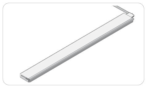
- 1 x zForce AIR Touch Sensor
- 1 x FPC cable with connector
- 1 x Interface board and an Arduino-compatible board
Additional required equipment:
An Arduino-compatible board. The I2C library described here supports most Arduino-compatible boards.
An Arduino development environment, for example Arduino IDE.
USB cable with a Micro USB type B connector
Make sure that the USB cable transmits both power and data and not only power.
- (Optional) tape for mounting
Required Equipment using Neonode Prototyping Board
- 1 x Neonode Prototyping Board
- 1 x zForce AIR Touch Sensor
- An Arduino development environment, for example the Arduino IDE.
USB cable with a Micro USB type B connector
Make sure that the USB cable transmits both power and data and not only power.
- (Optional) tape for mounting
Connecting Sensor using the Interface Board
- Connect the FPC cable to the interface board:

- Lift the flip lock on the interface board.
Insert the FPC cable into the end of the connector, with the connector pads facing down, towards interface board. The yellow piece of PCB of the connector on the other side of the cable is facing upwards. Make sure the direction is straight into the connector and the pads have reached the end of the connector.
Make sure the connector pads of the FPC cable are facing downwards, towards interface board. The sensor risks damage if the FPC cable is connected in wrong direction.
Press down the flip lock.
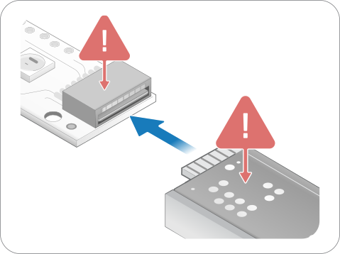
- Connect the FPC cable to the sensor:

- Place the sensor so that the sensor connector pads of the sensor are facing downwards (steel surface upwards).
- Insert sensor into the connector on FPC cable (yellow piece of PCB of the FPC connector still facing upwards).
- Make sure the direction of the pads is straight into the connector, and the pads have reached the end of the connector.
- Wire the pads of +5V, DR-B0, I2C-D, I2C-C, and GND on the interface board to the corresponding pins on the host system. For details, refer to Electrical Integration. Do not connect power until the following steps have been performed.
Make sure no object is within the touch active area of the sensor before connecting power to the sensor through USB. The sensor calibrates itself when powered on and an object within the touch active area may interfere with the calibration.
If the sensor is of the 0° type: place the sensor on a table with the steel surface facing downwards and with the optical surface facing towards you.

If the sensor is of the 90° type: place the sensor on a table with the steel surface facing upwards, so the optical surface is facing upwards as well. Make sure no object is within the touch active area above the sensor.

Alternatively, you can mount the sensor by using tape in order to fasten the steel surface of the sensor to the edge of a table, with the optical surface facing towards you.

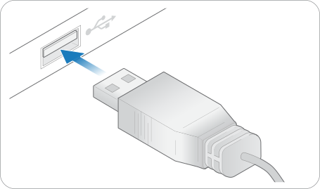
Insert the USB cable into a computer.

The green LED on the interface board lights up when connected.

Connecting Sensor using Neonode Prototyping Board
- Connect the sensor to the Prototyping Board

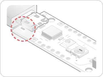
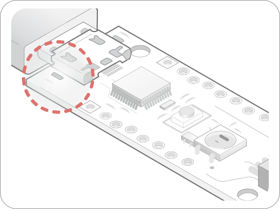
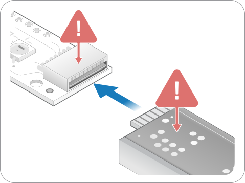
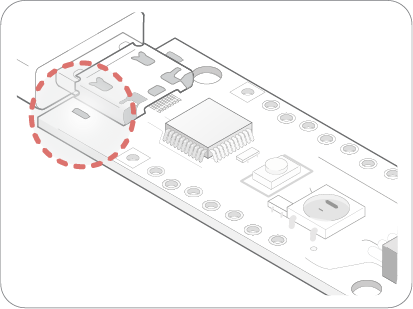
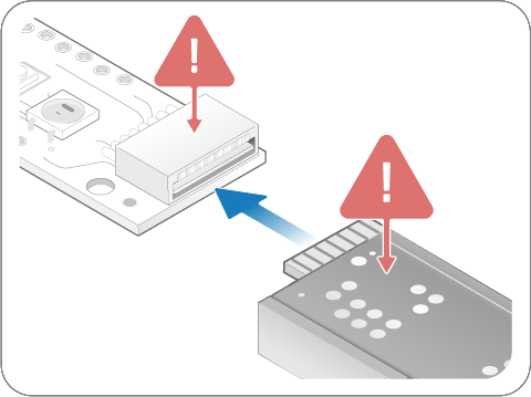
- Place the sensor so that the sensor connector pads of the sensor are facing upwards (black surface upwards).
- Insert the sensor to the sensor port on the prototyping board.
The sensor is now connected to the board, which expose all connections between the sensor and board. For details, refer to Electrical Integration. Do not connect power until the following steps have been performed.
Make sure no object is within the touch active area of the sensor before connecting power to the sensor through USB. The sensor calibrates itself when powered on and an object within the touch active area may interfere with the calibration.
If the sensor is of the 0° type: place the sensor on a table with the steel surface facing downwards and with the optical surface facing towards you.
If the sensor is of the 90° type: place the sensor on a table with the steel surface facing upwards, so the optical surface is facing upwards as well. Make sure no object is within the touch active area above the sensor.
Alternatively, you can mount the sensor by using tape in order to fasten the steel surface of the sensor to the edge of a table, with the optical surface facing towards you.
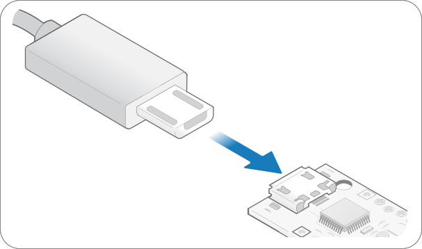
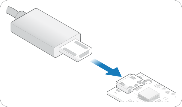
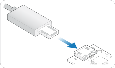
- Connect power to the sensor through the USB.

- A red light next to the micro USB port should turn on to indicate power transfer.

- A red light next to the micro USB port should turn on to indicate power transfer.
- The Protyping Board is now ready to be flashed.
- For further information, please refer to Get Started With Neonode Prototyping Board.
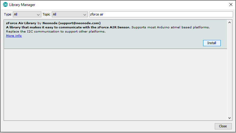
Arduino Library
Please refer to our Arduino Library.